A/C Troubleshooting chart

Thank you for visiting my blog I would appreciate any feedback I can get, Please leave a comment on whether my information has helped you. I am always interested in more topic to write so feel free to leave a comment asking about anything related to HVAC-R(Heating, Ventilation ,air conditioning, refrigeration).
Thanks for reading my blog
Air conditioning basics
Connecting Air Conditioning manifold
The gauges will have a high pressure (red) and low pressure (blue). The easiest way to remember which hose goes to the correct line is to think about a fluid going through the system. A smaller pipe size would need more pressure to move the same amount of fluid than a larger pipe size. So that would mean the smaller pipe will have the high pressure (red) hose from your manifold gauge set. While the larger pipe will have the lower pressure (blue) hose from your manifold gauge set. Yellow hose is for adding charge to you system, big black hose on 4-line gauge set is for vacuuming system down to 500 microns.
Approach Temperature method
This method can verify refrigerant charge without connecting a refrigerant gauge set. Before you begin the evaporator (inside coil above furnace) and condenser (outside coil) must be clean. You will find the approach temperature chart either in the manufacturers installation instructions or on the panel for the condenser. This chart will be specific to the condenser you are working on and will differ from other units.
Measure temperature of the air entering the condenser in a few places to get the average temperature being careful that the sun does not affect the measurements. Then measure the liquid line temperature (small line) with an accurate clamp thermometer. Determine the temperature difference between the liquid line temperature and the outdoor air temperature. The temperature difference is the approach temperature.
Adding refrigerant will decrease the approach and removing refrigerant will increase approach. Allow 10-15 minutes of operation for the approach to stabilize after refrigerant is added or removed. Insure you use proper recovery containers when removing refrigerant since it is against the law to release into atmosphere and comes with a big fine if caught.
Liquid line temp – ambient temp = approach temp
Superheat
Measuring Superheat tells you how effective the evaporator is working; normally best 10 to 15 superheat for air conditioning.
Superheat is the amount of heat added after the gas changes from a liquid to a vapor. Proper Superheat set point is important to an air conditioning system for these reasons
Low Superheat can cause liquid to get back to the compressor breaking internal parts.
High superheat will reduce the effective cooling, which happens best when liquid refrigerant changes state from a liquid to a vapor, also if too much superheat the compressor can overheat.
To measure superheat use the low pressure (blue) line of the refrigerant gauge set and clamp on thermistor to measure temperature at the suction line as close to the evaporator as possible. Suction line as close to evaporator outlet – saturation temperature of the refrigerant= Superheat
Subcooling
Subcooling tells you how effective the condenser is working normally you want 10 degrees subcooling but should always follow manufactures recommendations. Subcooling is the amount of heat removed by the condenser past the point of change from vapor to a liquid (saturation point). Proper Subcooling set point is important to an air conditioning system for these reasons.
Subcooling insures a solid column of liquid to the metering device and if set too low you could get flash gas, which will affect the meter device.
High subcooling will cause the refrigerant to stack up in the condensing unit bringing up the head pressure in the compressor. With higher pressures the compressor will need to work harder using more electricity and wearing it out faster.
Thank you for visiting my blog I would appreciate any feedback I can get, Please leave a comment on whether my information has helped you. I am always interested in more topics to write so feel free to leave a comment asking about anything related to HVAC-R (Heating, Ventilation, air conditioning, refrigeration).
Presures
High side is ambient plus 30. A 75 degree ambient, for example, add 30 and get 105 degrees. That, on a P/T chart converts to about 253 psi
Low pressure side should run about 10 degrees cooler than space set point.
Thanks for reading my blog
Recommended tools
Fluke 116/322 HVAC combo kit basic multimeter and amp clamp that will do anything in residential diagnostics.
Fluke 87V Digital Multimeter if you are working on any Engineer MUA (Make Up Air) or RTU (Roof Top Unit) you need the percent duty cycle option to set up combustion motor speed sensor properly.
Cooper SH66A Multi-temperature thermometer instrument. Good for measuring temperature on pipe or airflow
Ritchie Yellow Jacket LCD Vacuum Gauge 69075 senses the full range from atmospheric pressure down to 1 micron. I have had mine for 6 years and have never had any problems with it. It will give you exact number read out not just lights to indicate vacuum pressure
D-TEK Select Refrigerant leak detector this leak detector is the best one I have used it is very sensitive and will find the smallest leak. Some people believe it is too sensitive, because sometimes when it is moved fast it will beep. If you use the meter properly by moving it slowly around the leaks it will prove to be the best meter on the market. I would rather have a few false readings then to miss a leak that would cause me to return to the same job site a few times on callbacks.
Fluke Alert Voltage Detector A/C 90-1000 Volts-1AC-A1-II & A/C 20-90 Volts. I always carry one of these detectors around sometimes I can diagnose a problem with it or double-check the power for safety. Always test detector against known power and use meters to insure all power is turned off.
Testo 510 Manometer is the best manometer I have found that will measure differential pressures. The unit has many switchable units of measure. Very accurate as mine is 6 years old and has never required calibration. Only complaint is max pressure 1.5 PSI.
Powers Pneumatic Calibration kit 832-177 comes with Siemens adapters should buy Honeywell and Johnson adaptor kits as well in order to do all thermostats.
Procore Ratchet Wrench 17-9568 only 5 degrees of operation is needed to use this wrench. All wrenches have opened end and ratchet box end, which makes easy work in tight places.
If anyone has a better meter they use please send a comment to me and I will add it. I know fluke has a new one with flexible amp clamp, but I do not have the meter so I can’t comment on it
Thank you for visiting my blog I would appreciate any feedback I can get, Please leave a comment on whether my information has helped you. I am always interested in more topics to write so feel free to leave a comment asking about anything related to HVAC-R (Heating, Ventilation, air conditioning, refrigeration).
Thanks for reading my blog
Climate Master heat pumps trouble shooting
On left side of the control board will be the test terminals, short them with screwdriver and the diagnostic light will flash an error code
No power
- Starter or breaker tripped possible faulty compressor start windings, a hard start kit can be used to make unit work but with my experience it only lasts a few months.
2 Flash high-pressure problems red wires run to HP switch
- Water Condenser should have 10-degree difference between water going in and water going out.
- Refrigerant charge could be over charged check subcooling.
- Faulty high-pressure switch test switch at normal pressures it should be normally closed.
- In heating mode possible low/no airflow over the Evaporator.
- Faulty TXV bulb loss of charge or plug/stuck valve
My experience 1 Refrigerant 410a cooling H-600 PSI L-50 PSI and dropping frost between TXV and air coil, trip on high pressure Heating H-350 PSI L-75 PSI cold between TXV and water condenser, trip on water coil low temperature Found TXV stuck closed I replaced both filter/dryers, TXV, vacuum to 500 microns, new refrigerant system works perfectly now H-350 L-150
My experience 2 Refrigerant 410a H-350 L-125 high-pressure switch open. Faulty switch need to recover refrigerant replace high-pressure switch (one two red wires run to) and two filter/dryers. Leak test with 150-PSI nitrogen, Vacuum down to 500 microns. Recharge
3 Flashes low pressure/ loss of charge Blue & Brown wires to LP/LOC switch
Refrigerant charge lost due to leak
Most leaks will be found at the access fittings where we connect our gauges. I have found leaks at water condenser, Evaporator, and on copper line where they had rubbed against each other until it created a hole. If 0 pressure leak search with 150 Lb nitrogen repair leak vacuum all moisture out of system to 500 microns, recharge by weighing in refrigerant.
When arriving at a system you find it has 0 PSI Refrigerant pressure most likely the leak will be located on the liquid or discharge side of the system. Climate Master leaks are very hard to find in the past I have found them on the evaporator. Pressure tests may seem to hold due to the small leak, But if 0 PSI then you do have a leak. Look for oil stains anywhere on piping pressure test, refrigerant leak detector until you find the leak.
4 flashes Water coil low temperature limit grey wires to FP1 sensor
- Cooling mode reduced or no water flows to water condenser.
- Bad thermistor click here to see Temp/Ohm chart and compare. Temp/Ohm chart on page 11
- Faulty TXV bulb loss of charge or plug/stuck valve
My experience Refrigerant 410a cooling H-600 PSI L-50 PSI and dropping frost between TXV and air coil, trip on high pressure Heating H-350 PSI L-75 PSI cold between TXV and water condenser, trip on water coil low temperature Found TXV stuck closed I replaced both filter/dryers, TXV, vacuum to 500 microns, new refrigerant system works perfectly now H-350 L-150
5 Flashes Air coil low temperature limit Violet wires to FP2 sensor
- low refrigerant charge
- faulty TXV
- cooling mode reduced or no air flow.
- Bad thermistor click here to check Temp/Ohm chart and compare. Temp/Ohm chart in page 11
My experience
Blower motor seized or low air flow
low refrigerant Refrigerant 410a high-240 low-55 superheat 77 subcooling 0 Found high service valve leaking – replace cores and caps. Recharge unit with 2lb 6 oz high- 320 low-120 superheat 9 subcooling 10
6 Flashes Condensate fault Yellow wire to condensate sensor
- Blocked drain.
- Always have Trap installed next to heat pump.
7 Flashes over/under voltage
- Compare main power supply voltage and 24VAC before and during operation.
Thank you for visiting my blog I would appreciate any feedback I can get, Please leave a comment on whether my information has helped you. I am always interested in more topics to write so feel free to leave a comment asking about anything related to HVAC-R (Heating, Ventilation, air conditioning, refrigeration).
Thanks for reading my blog
Engineered air rooftop units
Engineered air pre-purge error
Combustion motor on engineered air units are variable speed, which are controlled by the hertz to the motor. Voltage will always remain constant and to slow down the motor the DJM2 controller will run between 15-59 Hz. If the reading it over 59 Hz then the speed sensor is grounded and the wire and/or sensor need to be replaced, 3450 RPM equals 59 Hz.
- If combustion motor is running first check tachometer signal, Y to G should run between 4-6 VAC. If AC is not present check that the sensor is 1/16 inch from magnet at the end of combustion motor shaft. Also insure the sensor is not over the centre of the shaft, But rather it is off to one side of the magnet.
- If voltage is within 4-6 VAC, The DJM2 is sensitive to the shape of the waveform produced by the speed sensor. You will need a fluke 80 series similar multi meter that can measure percent duty cycle. Connect meter to Y and G press Hz for Hertz then second time for duty cycle. Speed sensor will output a signal close to 50% duty cycle and must be accurate within 2.5%. If the number is outside those parameters the pre-purge problem light will flash
- Many time the only thing wrong with this system is the magnet at the end on the motor shaft. By flipping over the magnet sometime will fix the problem

Thank you for visiting my blog I would appreciate any feedback I can get, Please leave a comment on whether my information has helped you. I am always interested in more topic to write so feel free to leave a comment asking about anything related to HVAC-R (Heating, Ventilation, air conditioning, refrigeration).
Thanks for reading my blog
Combustion air
Combustion/Dilution air is required on all gas appliances; always include hot water tanks total BTUH input in the calculation. If hot water tank is the only system requiring combustion/dilution air then it is only required on over 50,000 BTUH units.
Fresh air (make up air) is required on every home with any type of furnace. Fresh air is connected more than 1 meter from the drop of the return air for the furnace then connected outside. If the fresh air is connected closer to the drop than 1 meter it will cause cold air to be brought into the room even without blower motor running.
High efficient furnaces do not use combustion air from the room as they have two pipes to the outside one exhaust air and one combustion air. Sometimes only one pipe (exhaust air) goes outside in this case the furnace will need combustion air brought in to operate properly.
These sizes are to be used at your discretion, as it may be different depending on local codes
Tight structure design
Combustion air inches round duct – total of all appliances BTUH inputs
3-inch – 25,000/50,000 4 inch – 75,000/100,000 5 inch – 125,000/150,000 6 inch – 170,000/225,000
Combustion air pots must be located within two feet horizontally and level to within one foot above the burner of the appliance with the largest BTUH input rating
If you find cold air being drawn in from either the combustion or the fresh air I recommend getting a Hoyme motorized damper that will only open on a call for heat. hoyme website Shell Busey and Cliff Hoyme Explain the Motorized Damper
Combustion and fresh air outside terminations have a mesh that need cleaning annually. Check out picture of fresh air intake under deck
Click here to see my Post on protecting your home “Alarm for Home”
Thank you for visiting my blog I would appreciate any feedback I can get, Please leave a comment on whether my information has helped you. I am always interested in more topics to write so feel free to leave a comment asking about anything related to HVAC-R (Heating, Ventilation, air conditioning, refrigeration).
Thanks for reading my blog
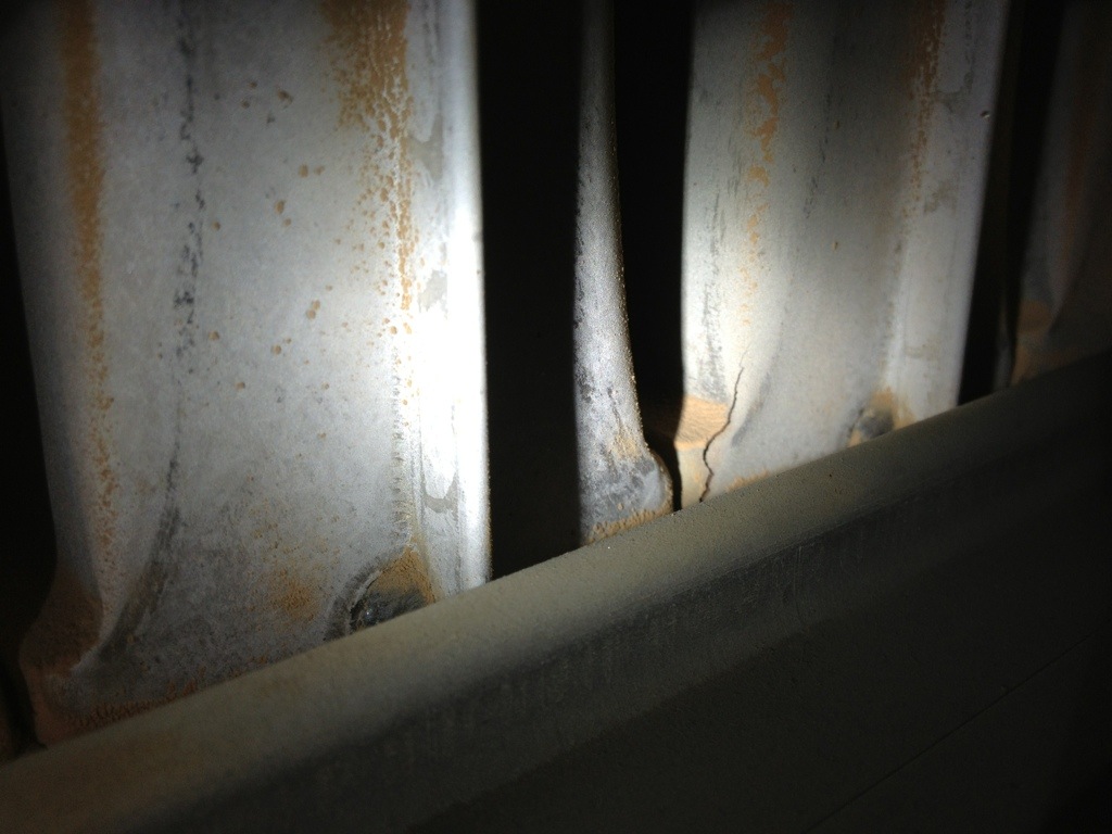
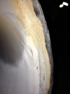
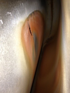
Cracked heat exchanger
Heat exchanger can crack for various reasons and should be checked every time furnace is repaired or maintained.
Visually check heat exchanger for cracks
- You will find most cracks form near the back and where the heat exchanger metal bends, Since this is where it will be weakest due manufacturer weakening the metal by bending it.
Watch the flames as the furnace fan starts if you see the flames are blowing around or out the front of the burners then you will need to take a closer look at the heat exchanger
Water test
- This test worked best on the old Lennox G8 and would find cracks or pinholes on the heat exchanger that sometime could not be seen.
If there is no air conditioning then it will be easy to access above the heat exchanger through the humidifier. Once the heat exchanger cools down spray water on the heat exchanger from the top insuring full coverage and being careful of the electronics and motors. Then watch inside the burners for water to seep through, A good heat exchanger will not let moisture into burner chamber
Using carbon monoxide detector
- Test for carbon monoxide at return air as well at supply air and compare the two readings or test at supply air with burners on then off making sure furnace is not back drafting and compare.
If you take reading once and only at supply air you will not be 100 percent sure the problem is with the heat exchanger. You are testing the accumulation of carbon monoxide over a long period of time from other sources like the furnace or hot water tank back drafting also it could be from outside sources like a vehicles near the intake air.
Reasons for cracks
- If the furnace does not have enough combustion air it will cause the furnace to run hotter then designed. Then with more expansion and contraction in the heat exchanger it causes cracks. The gas pressure must be set as per furnace name plate derated for location altitude if too much gas heat exchanger will run too hot.Blower speeds must be checked by comparing furnace temperature difference to name plate rating if running too hot increase fan speed and recheck temperature supply air minus return air.
.
Any crack in a heat exchanger is dangerous and the heat exchanger must be replaced when crack is found

Click here to see my Post on protecting your home “Alarm for Home”
Thank you for visiting my blog I would appreciate any feedback I can get, Please leave a comment on whether my information has helped you. I am always interested in more topic to write so feel free to leave a comment asking about anything related to HVAC-R (Heating, Ventilation, air conditioning, refrigeration).
Thanks for reading my blog
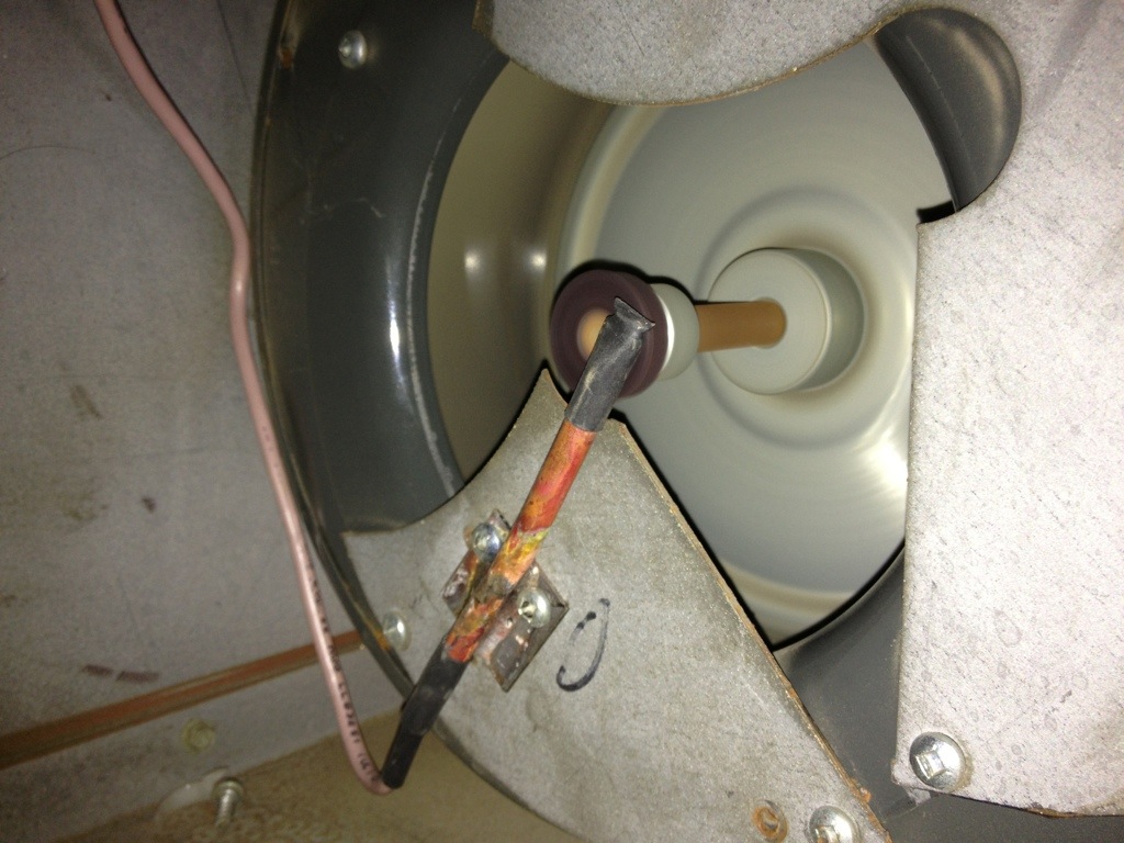
Pressure switch
Pressure switch is the safety device that proves the ventor motor is working (motor above burners connected to vent). It has vacuum lines that are connected from the pressure switch to the ventor motor that measure a neg air pressure. All furnaces will have different pressures required to operate properly, most times the pressure will be written on the switch measured in inches water column.
Problems with pressure switches
- Vacuum lines port plugged
You will get open pressure switch error code, It can easily be fixed then you should reset the furnace to delete error code.
Over time moisture will build up in the vacuum line port then dry up causing it the plug off. I have found the build up on the motor side of the vacuum line that was bad enough to shut down the furnace causing no heat. The vacuum line can be removed and the hole cleaned out with a small Alan key or anything small enough to fit in the hole with out breaking off. After cleaning it out you would need to shut power off at the furnace power switch to delete error code. - Pressure switch fails closed
Normally this would indicate a failed pressure switch, The furnace will test to make sure the switch is open before starting the ventor motor. The contacts in the switch are either stuck together or moisture has entered the switched and seized it in the closed position. The switch will need to be replaced then you should make sure the vacuum lines are sloped back to furnace so water will not enter the switch again. - Pressure switch fail open
First and most obvious would be failed ventor motor, check 110 volts to motor and if it has seized.
The most common problem on high efficient furnaces would be frost or water in the vent. First off the furnace being high efficient will produce water due to low vent temperatures and condensation in the vent pipe. Motor ventor motor has been replace recently then make sure orfice plate after motor is in place - Water I do not like horizontal vent pipes on furnace but sometime they must be done. If the pipe sages a little and water collects it will block off the pipe, Very important to have the pipes properly supported. When the Vent pipe is repaired it should drain back to the furnace where the water will be routed to a floor drain.
- Frost the exhaust on the furnace is warm and moist, sometime the intake which is very close to the exhaust will suck in this warm moist air and mix it with cold air producing frost. Frost will plug up the intake pipe causing the furnace to fail, the exhaust vent should be extended 8 inches past the intake. Also you should be careful of fences and other obstructions the exhaust could rebound back to the intake pipe.
- Faulty switch
Anytime I am working on a furnace or during maintenance I will test the pressure switch for faulty contacts. I will start the furnace up and when the burners are on lightly tap the pressure switch if it stops the furnace then it should be replaced since contacts are not making a good connections internally.
- How to test the pressure switch
Pressure switches are on the safety circuit of the furnace so that means it is 24 Volts a/c. Test from common to either side of switch when motor is running you should have 24 volts on each side. Once it is established you have power then you can connect meter similar to the way I have on the picture below. Connect Positive to one side and Negative to the other, when the ventor motor is running the meter will read 0 Volts. If you have 24 Volts, the pressure switch is open and not proving the ventor motor. Or you test any Voltage between 1 to 23 Volts then you have bad contacts and the full power is not getting through causing the furnace to fail. On a few furnaces I have found the ventor motor seams to be running fine and power is good but fails on pressure switch. When this happens it is best to record the Voltage from one side of the pressure switch to the other because the motor could drop rpm for very short time. The short drop in power is enough for circuit board to notice but not enough for you to notice.

Click here to see my post on protecting your home “Alarm for Home”
Thank you for visiting my blog I would appreciate any feedback I can get, Please leave a comment on whether my information has helped you. I am always interested in more topic to write so feel free to leave a comment asking about anything related to HVAC-R (Heating, Ventilation, air conditioning, refrigeration).
Thanks for reading my blog
Flame Sensor failure video
In this flame sensor video you will see the sequence a furnace will take when you have a flame failure. The burners will try to light 5 times then go into lock out for 3 hours before it will try again. Another thing to keep eye on is the diagnostic light on the circuit board of the furnace located middle to the left side. You will see it flashing different codes count the flashes as it changes 4 times. short and long flashes
- 1st code 12 meaning blower delay time, will change to next code solid light on after 34
- 2nd code will be on solid for call for heat, flames fail and change to code 34 after 50 sec
- 3rd code will be 34 for ignition proving failure, will change to code 14 after 4th try to ignite after 2 min 48 seconds
- 4th code 14 ignition lockout. The furnace will be locked out for 3 hours before it tries again, you will need to reset power for furnace to try again by shutting power off then back on after a couple minutes or turning temperature down then up again.
95 percent of the time the problem is only a maintenance issue and just needs the flame sensor cleanedClick on this link to see the video furnace flame failure video
Click here to see my Post on protecting your home ” Alarm for home”
Thank you for visiting my blog I would appreciate any feedback I can get, Please leave a comment on whether my information has helped you. I am always interested in more topic to write so feel free to leave a comment asking about anything related to HVAC-R (Heating, Ventilation, air conditioning, refrigeration).
Thanks for reading my blog

